Bit #27: Second experiment: how fast can a mining chip respond?
In progress: a three-board bench of Antminer S21 chips, and the power meter I built for it
This post describes the second experiment of the project, which is still in progress. The first post explains why the project exists. The first experiment measured how fast an AI GPU's power changes, and then simulated miners offsetting those changes. In that simulation the miners' time constant ranged from 0.2 to 5 seconds. Nobody has published how long a mining chip takes to settle at a new power level after a change in its clock frequency. This experiment measures it.
The hardware
- Boards: three Bitaxe Supra boards. A Bitaxe is a small open-hardware Bitcoin miner. Each Supra carries one BM1368 chip, which is the chip inside Bitmain's Antminer S21.
- Two board revisions: one board is revision 403 and two are revision 401. The two revisions supply power to the chip through different circuits. The measured response includes the board's power circuit, so I will report the two revisions separately.
- Scale: a Supra draws 15 to 20 W at 5 V. An S21 draws about 3.5 kW through a large power supply that adds its own delay. The bench measures how fast the chip and its board's small power circuit respond, without a large power supply in the path. A production machine still has to be measured separately.
The method
A mining chip's power approximately follows this equation:
P = F + k V² f
- P is the board's power.
- f is the chip's clock frequency. It is the only setting I change.
- V is the chip's voltage. I hold it fixed.
- k is a constant set by the chip's design.
- F is the power that does not change with the clock: the power supply, the fan, the controller, and the current the chip leaks even when it is not switching.
The chip's leakage current rises with its temperature, so F is not exactly constant. I hold the fan at a fixed speed to keep the temperature as steady as possible.
In each test I command the clock to step down, and later to step up. The board's power changes after each step, with a delay. I measure the time the power takes to go from 10% to 90% of its change. That time is the settling time.
The predictions
As in the first experiment, I wrote the predictions down before running anything:
- The settling time for a frequency-only step will be under 50 ms.
- Settling will be asymmetric: a step up in power will settle more slowly than a step down.
- Because of F, the board's power will change by a smaller fraction than the frequency does.
- The chip will offer a set of separate frequencies, with visible gaps between them.
- Three boards stepped together will sum to within 5% of the sum of their separate steps.
The power meter
To time a step that may last only milliseconds, I need a meter that reads each board's power many times per second. I built one from these parts:
- Three Adafruit INA228 power-sensor boards, one in the supply line of each Supra. Each sensor measures the current through a 15 mΩ resistor, and the voltage on the line.
- One Adafruit QT Py RP2040 microcontroller. It reads all three sensors over a single I²C bus and sends the readings to a laptop.
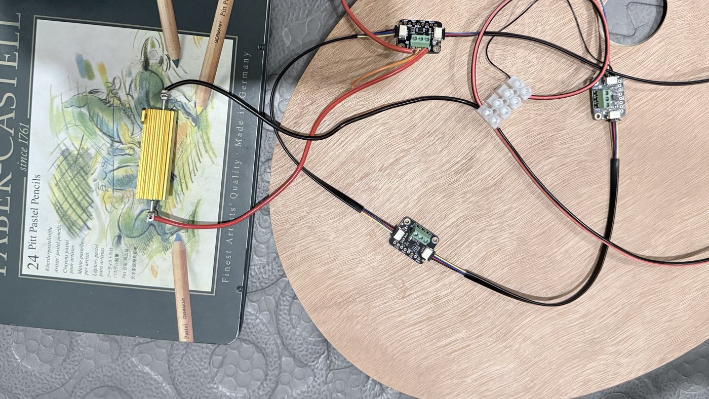
- Three short supply-line connectors that I made. Each connector routes one board's power through its sensor.
Progress so far
- September 25: the parts arrived.
- October 10: the microcontroller found all three sensors on its bus. The first scan failed because one cable was loose. All three sensors accepted their configuration and returned it correctly when read back.
- October 10: the first connector had been built on October 1 with its two red leads swapped. A photo from that day shows the mistake. I corrected it on October 10, and it then passed all six continuity checks. I powered the meter from my bench supply at 5.00 V, with a 0.20 A current limit and nothing attached.
- October 10: I connected a 2 Ω resistor as a test load. The first test drew only 1.68 A, which implies about 1 Ω of resistance in the loop beyond the resistor. I measured the voltage drop across each part of the loop. The largest drop, 0.70 V at about 1.9 A, was across the test leads supplied with the bench supply. Those two leads together measured about 0.36 Ω. I replaced them with 18 AWG wire. After that, the section of the loop that holds the resistor measured 2.04 Ω.
- October 11: the first sensor read 2.169 A. The bench supply showed 2.17 A, a difference of 0.03%. My multimeter read 2.21 A, a difference of 1.84%. That difference is inside the multimeter's stated accuracy at this current, which is about ±2.6%.
- October 11: I built the second connector and checked the second sensor the same way. It read 0.46% below the bench supply and 1.84% below the multimeter. Both sensors differ from the multimeter by the same 1.84%, so the multimeter probably reads about 1.8% high.
These checks cover current only. I have not yet compared the sensors' voltage readings with the multimeter.
Two problems to check before the chip tests
- The bench supply. My bench supply is a Korad KA3005D. A published test of the same model measured an oscillation close to 2 V under a pulsing load. That oscillation is larger than the whole signal this experiment records. I will not use the bench supply to power a settling-time test until I have measured its response on my own unit. I will keep using it to check the meter.
- A ground loop. On a Supra, the ground of the USB port and the return of the power jack are the same connection. Mujina controls each board over its USB cable, so the USB cable is connected during every test. Part of each board's return current can therefore flow through the meter's sensor cables, which are rated for 1.0 A. I do not yet know how large that current is. My estimate for three boards is between 0.12 A and 1.3 A, and it rests on a USB cable resistance that I have not measured. I will measure the current before running three boards together.
Next
- Build the third connector and check the third sensor.
- Power the first Supra through the meter, from a 5 V power adapter.
- Write the meter's fast logging mode, which reads each sensor about 1,000 times per second.
- Test the firmware that changes the chip's clock while the chip mines.
The firmware
The boards will run a modified version of Mujina, the 256 Foundation's open-source Bitcoin mining firmware. Mujina is written in Rust and licensed under the GPL. Its authors take no developer fee from the mining revenue. Mujina runs on a computer that is connected to each board by USB. Today it supports one Bitaxe model, the Gamma, and it has no controls for clock frequency, voltage or power.
I am adding three things:
- Support for the revision 403 Supra and its BM1368 chip. The code is written and has been reviewed. It has not yet run on a board.
- A command that changes the chip's clock frequency while the chip keeps mining. This is the control the experiment needs. The code is written and has been reviewed. It has not yet run on a board.
- Support for the revision 401 boards. Each Supra has an ESP32-S3 microcontroller. A Supra as shipped runs its own standalone mining firmware on it. To work with Mujina, the ESP32-S3 must instead run a small open-source firmware that passes commands from the computer to the chip. On revision 401 boards, that firmware never switches on the circuit that powers the chip, so the chip cannot mine. I will modify that firmware and publish the modified version. I have not started this part.
